
If your intention is to work on most any circuit using the ancient and outdated technology known as the vacuum tube, you're going to need a couple things. First, a low voltage, but reasonably high current supply of AC to run the tube heaters. Second, a 'plate' or B+ supply of a hundred volts or more to drive the tubes. In smaller circuits, such as simple oscillators, low power audio amplifiers, and radio receivers, the current sourced by the B+ supply doesn't have to be particularly great. Thus, designing and constructing a suitable supply is simple.
One common problem is that the B+ supply is generally fixed at some certain voltage, or switchable (usually via transformer taps) to some number of levels, perhaps two or three in number. A continuously variable voltage can be obtained by using a large potentiometer to act as a voltage divider, but these are not always the easiest thing to come by. Still another solution is to put a variac in line with the 120 VAC mains feeding the transformer primary. This works nicely, except to the casual experimenter's wallet; a Variac can set you back a couple hundred dollars. Let's keep this cheap and cheerful, shall we? Finally, one could build a large saltwater rheostat, and put that in the 120 VAC mains circuit. That should work, if done right, but you may not be keen on having a large, open basin of conductive saltwater connected to the mains circuit. What happens if you spill it? Nothing good.
Fortunately, there's a simpler, if somewhat inefficient and odd way to have a continuously variable voltage, in two stages (which overlap, so no gap exists), by using a handful of additional components, including a pentode tube, and a neon bulb.
Now, it's generally considered bad form to make a B+ supply intended to drive vacuum tube equipment with solid-state (diode) components. Can it be done? Absolutely. Should it? I'll defer to my muse for that...
"No. Diodes can be killed by startup transients in tube circuits. You could guard against this...... but why would you want to when vacuum tubes are, like, so cool? And they're like this totally romantic part of history! All glassy, and glowy, and warm, and pretty, and--"
Far be it for me to disagree with that. So while she's going off on that tangent, I'll just go ahead and hand over the schematic.
You'll notice we've got two power supplies in one; the variable B+ supply itself, and a separate, AC filament supply, two legs of which give 6.3VAC apiece (a common heater voltage), around a common neutral. These can be used together, neglecting the common neutral, to give 12.6VAC, used on some tubes (12DQ6, etc.), or if you have a tube which uses a lower voltage, say 5 volts (5Y3GT, etc.) or even 2 volts (old 32, if you're brave enough to run it on AC), you can use a series resistor to bring the voltage across the tube's filament to a lower value. Start with a resistor with too high a value, and measure the voltage across the filament, and slowly lower the resistor's value until the proper voltage is obtained. Do this slowly and carefully; here at United Neko, tubes are damned near sacred, and we do NOT take the idea of overcurrenting a filament lightly. Another good practice is to use a resistor even if the tube filament matches the 6.3VAC output; running the filaments just a tiny bit cooler will not noticeably reduce performance, but it will noticeably increase tube lifetime.
For the B+ supply itself, we have a transformer, robbed from discarded equipment, with two windings, one a 6.3 VAC filament winding, which is current limited via a resistor to power the rectifier filaments, and a 550 VAC center tapped winding. This winding feeds AC to a 5Y3GT vacuum tube rectifier, where it is converted to DC. With a simple LC pi-filter, the DC is smoothed, and sent to two destinations: first, a B+ unregulated, uncontrolled output for 'brute force' driving of whatever you might wish to power. Depending on the load, this can be up to 350 volts with parts and transformer similar to that which I used. Be careful.
The other output, the variable one we are most interested in, is created by sending the B+ to a 6F6 metal tube power pentode. Variable voltage control via a 1Mohm potentiometer is handled by varying the control grid voltage. The range settings, set by the DPST "HI/LO RANGE" switch are set by varying the reference on the screen grid. In the low setting, the screen grid is connected to ground with a neon indicator, similar to an NE-2; not all of these are alike, so some selection for proper voltage coverage is needed here. The range selection and voltage adjust potentiometer should work to cover all voltages, with no blind spots. For instance, if the low setting covers 10V to 130V, the high setting should cover, say, 120V to 300V.
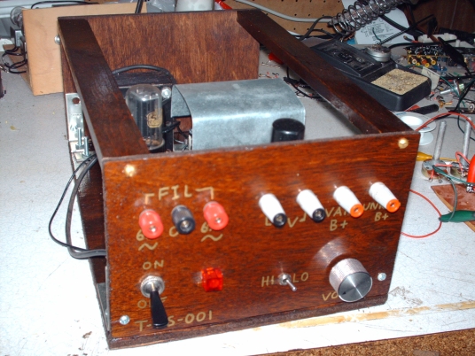
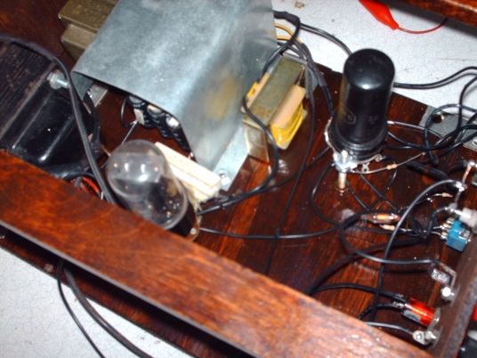
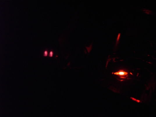
It isn't the prettiest thing, nor the most efficient, nor the best for supplying current, but for the radio projects I frequently work on, and simple oscillators and low power amplifiers, it hasn't failed me. Total cost was less than $20. All tubes were salvaged from derelict equipment, the wood used for the construction was from scraps found in my workshop, with money spent on only what little things were needed here and there to complete it. Below are pictures of the one I built. Yes, I built it open frame, and for two reasons. One, ventilation; the transformer and rectifier tube can get quite warm if powering a load for some time. Two, as my muse points out, why would you want to hide those pretty tubes from view? The last photograph, taken in a darkened room, shows the lovely glow.
Last updated July 26, 2010
This Web Page Created with PageBreeze Free HTML Editor