-Or-
How to confuse people with a simple machine
Most of you who are familiar with the electric motor would wager that in order to get rotary motion out of something electrically powered, you would need a set of electromagnets, either as stators, armature windings, or maybe both. Throw in a commutator or some switching circuit, and perhaps a few permanent magnets.
If you're a little more out on the edge, you might suggest that none of these are needed; just a source of high voltage and some properly shaped foil and plastic pieces, in which case you're thinking of an electrostatic motor. What I'm going to describe here is something quite different, and not well understood, although a lot of people claim to know why it works. C'est la vie.
Consider this crude diagram:
Doesn't look too impressive, does it? You've got a shaft, two ball bearing assemblies, a flywheel of some kind, and some other stuff to hold it together. And yet this thing, if properly constructed, is an electrical motor. It will spin, and quite fast, assuming you give it enough current.
What kind of current source do we need here? A car battery will do, assuming it is well charged and has a peak current rating of at least a few hundred amperes. Another good source of power for the motor is a "12V jump starter" pack, commonly sold at automotive parts stores, some hardware stores, and so on. These usually contain a lead-acid or lithium rechargeable battery, and can give 12 volts DC at several hundred amperes for a moderate amount of time, certainly long enough to run this experiment. They usually come conveniently with an internal charger supply that you can plug into any standard wall outlet.
WARNING! Drawing currents of this magnitude from a battery is not the safest thing. Batteries can and do explode under stressful conditions. Wear eye and face protection.
So we've got a power supply. Let's hook it to our gizmo and see what happens. Current goes into one ball bearing outer race, which is held stationary, travels through the ball bearings themselves to the inner race, passes through the metal shaft and into the inner race of the second bearing, through the ball bearings, into the outer race, and returns to the supply. How on Earth could this thing begin to rotate? It can't...
...unless you give it a spin first. Regardless of polarity, give it a flick of your hand, in either direction, and it will begin spinning. If the resistance of the setup is low and the current sufficiently high, the motor will accelerate quite rapidly. What's going on? I leave that as an exercise for the reader, but in this author's opinion, it is not due to heat, as is commonly assumed. Horace Heffner, another researcher, has conducted this experiment using nonmagnetic stainless-steel bearings and found NO acceleration. See this link. In my mind, this is indicative that the effect is not thermal, but magnetic. Regardless of WHAT it is, it is certainly entertaining to play around with, and makes an agreeable lab curiosity to show friends and family.
Now, here's something a bit more interesting. Notice how it will rotate in either direction, regardless of DC polarity. Well, might it work on AC? The answer is yes, and if you wish to study this any further, let me suggest that you use an AC supply. I describe a suitable one below, illustrated by one of my terrible drawings:
The core of this toroidal power transformer is composed of about four standard-sized rolls of black iron rebar tie wire. A form was made of two plywood disks and a spacer of PVC pipe of the diameter intended for the torus 'hole.' Tie wire was wound around this to form a donut shape. Once wound, the plywood disks were carefully removed, and the torus of iron wire wrapped tightly with cloth medical tape over its entire surface. This core will support quite a bit of power. Now, we must wind a 120 volt primary. (NOTE: this assumes you are using 120VAC 60 cycles. If using 240VAC 50 cycles, I cannot speak with great experience... perhaps double the number of turns I suggest, and maybe reduce the wire gauge).
The primary I used was about 250-300 turns (sadly I did not keep accurate count) of #10 AWG THHN insulate stranded copper wire. As you can imagine, winding such a thing around a toroidal core is not fun. Wear gloves or you will quickly tear the skin of your hands to ribbons.
Once this is wound, a secondary can be wound. Fortunately, at least here in the states, a source of heavy, high-current-capable copper wire exists: car audio shops. There are these kids, you see, who put 'systems', as they're called, into their cars and blast music at ear-splitting volume. (Tris comments here: "ESPECIALLY ear-splitting if you have ears like mine!!!) The wire I obtained was not marked for gauge (!) but was insulated in a clear red rubber, and was approximately 1/2" diameter. I wound about 10 turns around the toroidal transformer. A previous incarnation used a pair of split automotive jumper cables as the secondary, connected in parallel or series, depending on voltage or current demand of whatever device was being tested.
The primary was plugged directly into the 120VAC mains, which produces a nice hum. The secondary of heavy wire is connected via heavy copper clamps to the terminals of the ball-bearing motor, which is then quickly given a spin. As can be easily seen by the experimenter, rotation in either direction is possible. Now you do not need to worry about messy and possibly explosive batteries.
A few pictures are here: (ignore the dates, they are incorrect... I was too rushed to set the date and time on the camera)
The first picture shows the general layout of the motor itself.
The power transformer is the gray wirewound torus in the upper right. This was the original incarnation, using paralleled auto jumper cables as the secondary.
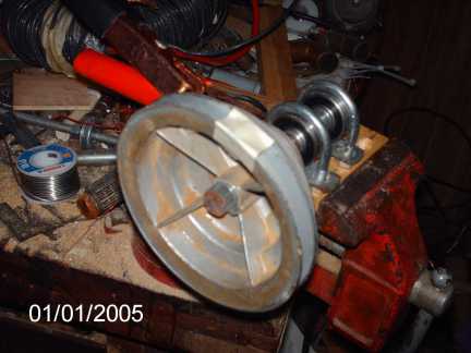
Motor profile. The piece of white tape was affixed to the flywheel to get a feel for how fast it was rotating.
Here is a link to a video of this motor operating, uploaded to YouTube. The video was taken about nine months ago, but doesn't differ appreciably from the newer versions I've tested.
An interesting note:
In further investigations of this strange motor, I decided to try a different bearing configuration. Instead of the usual ball bearing assemblies, I obtained two sets of older style conical roller bearings, as are commonly used in 1980's and prior automobile wheel bearings. They were magnetic through and through, as were the ball bearing assemblies I had previously used successfully.
They produce no detectable torque! Why? I don't know. I would have expected at least something from them. What is it about spherical ball bearings that causes torque, but is not available with these conical rollers? I invite anyone willing to conduct their own tests of this to do so, and do let me know the results.
A further experiment:
It was suggested by a fellow science enthusiast on a discussion group I am a part of that an interesting experiment would be to make an "inverted" ball-bearing motor. That is, instead of having the shaft rotate, hold the shaft stationary and let the stator rotate around it. The idea, illustrated below...
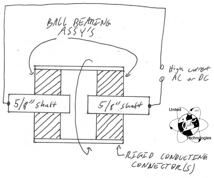
...is something like this: cut the shaft in two, and make both outer races of the bearings common. Current is then fed to each shaft-half. If it rotates, 'something odd' is going on, it was suggested. Being not much of a theoretician myself, but a most curious experimenter, I decided to make a quick-and-dirty version of this and test it. Watch the video of this test here on youtube, or download it here.
Tris comments: "Curious experimenting is what ended up getting everyone, regardless of where you come from, where we are! If no one asked questions, what answers would there be to find? ALWAYS look for new things!"
The result? As this video shows, the "inverse ball-bearing motor" works. What does it mean? I don't know. I leave that to others to determine for the moment. Happy experimenting!
This Web Page Created with PageBreeze Free HTML Editor