In addition to the simple TRIAC chopped HV supply, there's another common design family to be seen online for driving ignition coils. An active element, either a bipolar transistor or MOSFET is used to chop current through the primary of the ignition coil, with the active element controlled by a variable frequency audio oscillator. Usually the ubiquitous 555 timer is used. Nothing wrong with that, it's a fine chip, and can handle quite a bit of output current if the correct chip is chosen. The one you most likely want is the NE555N, which can sink or source 200mA, and that ain't anything to sneeze at. The LM555 will not do anything near this, and is more easily killed in my experience. Caveat emptor.
Here at United Neko, we commonly use a 4046 VCO driving a 4528 one-shot, to provide both frequency and duty cycle control, but...
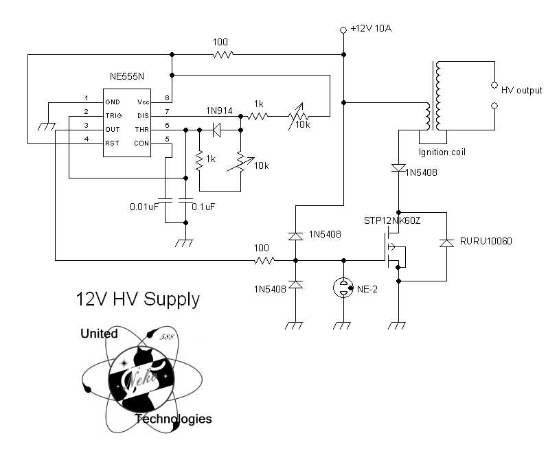
The active element is usually depicted as a 2N3055 if a bipolar transistor, or something like an IRF510 if a MOSFET. These are generally fine, but the experimenter will find to her/his dismay that both transistors and driver circuits are being destroyed at a greater than reasonable pace. There is a solution to this, it is simple and cheap, and I hope it will be of help to those of you reading this. I have taken a common design, and using parts we had on hand, added a few things to protect inputs and keep the back EMF from whacking the MOSFET too hard.
Pretty simple, and we still use the good NE555N timer here. The MOSFET, manufactured by ST Microelectronics, is quite a bit beefier than the IRF510; this one will handle 650V and can control currents of up to 10A. In short, this is not a part to be taken lightly. It is internally protected by zener diodes, but I beseech you, take this to heart: do NOT RELY ON INTERNAL PROTECTION! Always, always provide something external to protect the device, and leave it's internal protection as a weapon of last resort.
Another modification not too commonly seen is the addition of a 1N914 diode across R2. This causes the 555 to be operable over almost the entire range of duty cycle, not just 50 - 100%. With some coils, this can be very useful.
R1 and R2 control frequency and duty cycle of the 555 signal generator. The 0.1uF cap can be changed to other values to change base frequency of the oscillator. Experiment with this to suit your needs, and get the best output from the ignition coil.
Two 1N5408's function as protection for both the gate of the MOSFET, and the 555 circuit from back spikes of voltage that may be induced. These two diodes will keep voltages along the gate-trigger path from rising much above the 12V rail, or below 0V. 1N4007's work OK too, but if ultrafast recovery diodes are available, by all means, use them. The faster the diode, the better.
The third 1N5408 is a simple steering diode to help keep current through the coil flowing in the right direction. The RURU10060 is a monster diode, ultrafast, rated 600V at 100A continuous. This protects the MOSFET from reverse voltages, which will appear due to inductive kickback from the ignition coil. Instead of appearing across the MOSFET and it's delicate inner structure, the EMF will be shunted to the rails, where it can do much less harm. Again, the faster the diode, the better. This one is more than enough, but we had quite a few on hand for another project.
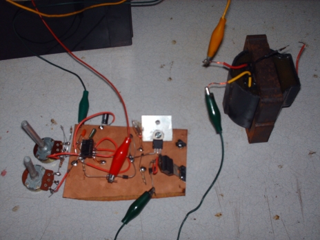
And don't leave out that NE-2 neon bulb. You might get away with it with the shell-core "true" transformer type ignition coils, but in my experience, the autotransformer-like can-coils have a much bigger problem with HV spikes finding their way up and into the sensitive gate of the MOSFET. The neon has, in my experience, eliminated this. It'll also blink every now and then, which is a nice touch in any case. The finished circuit, constructed "ugly" style and hashed together quickly is shown here. The black object in the upper left is a 12V lead-acid battery.
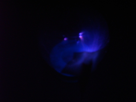
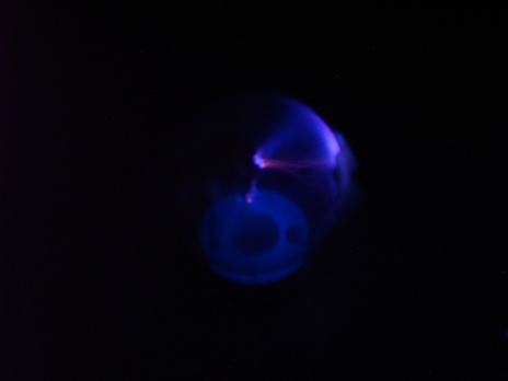
And now to see how it performs:
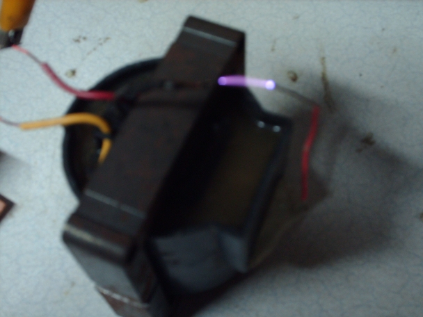
Driving an incandescent light bulb to make a poor-man's plasma globe. Due to the limitations of the camera, and the difference in the way it and the human eye percieve color, the picture appears more bluish than it actually was; in reality, it is far more lavender, and much more beautiful to observe:
Note that, as in the TRIAC dimmer HV design, two coils can be connected with their primaries in antiparallel, to give approximately double the output voltage.
Last updated July 26, 2010
This Web Page Created with PageBreeze Free HTML Editor